![]()
![]()
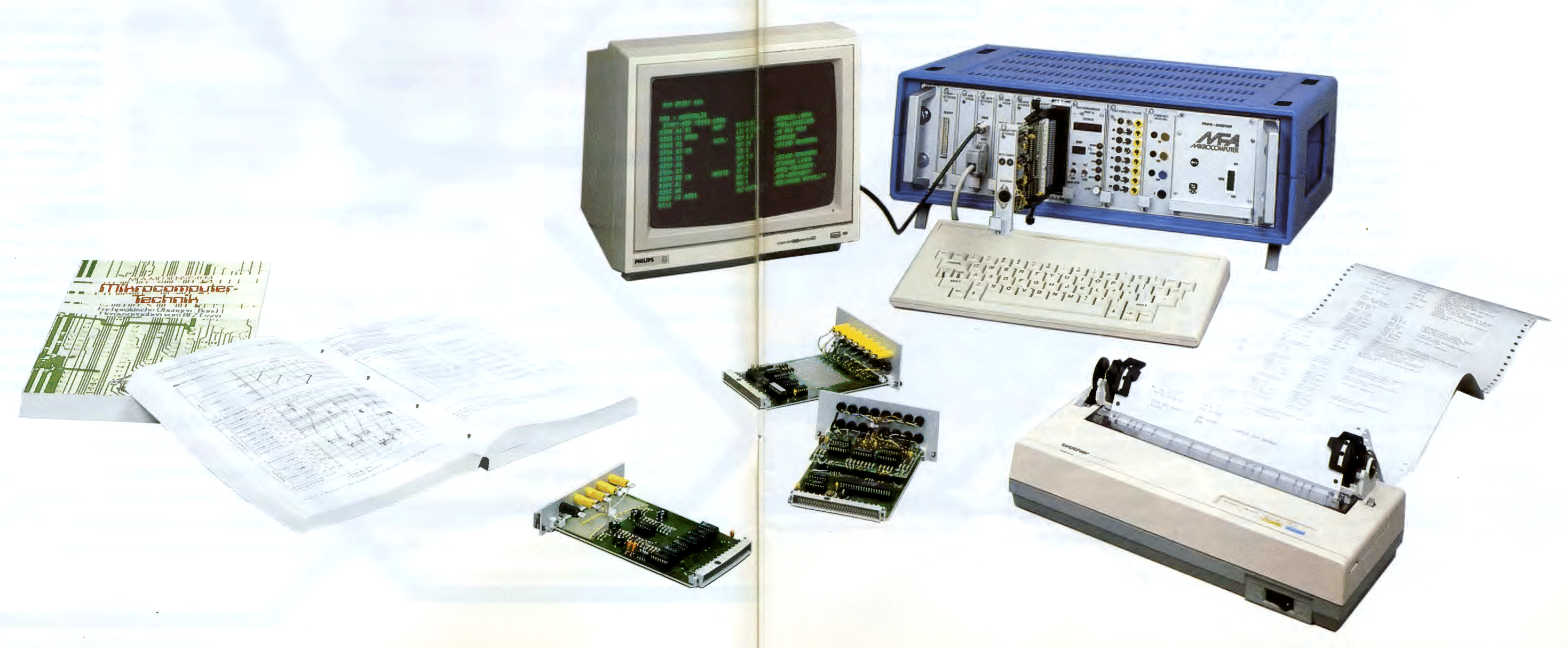
This neat microcomputer was made for training, education and schooling. It was published in Germany by the "Berufsfortbildungszenter Essen" ("Professional training center Essen") around 1984. It's powered by an Intel 8085 processor at 2MHz clock speed and is modular in many ways. This computer really helps understanding how microcomputers work and is a great tool to learn assembly. Together with its monitor program expansion you can even use a BASIC interpreter, or with a different BIOS and a floppy disk controller board run DOS or CP/M.
Because the Computer was almost only used in Germany, most of the documents and images are written/labeled in German.
A typical workplace of the MFA computer can be seen in the first picture, followed by my system in the second picture:
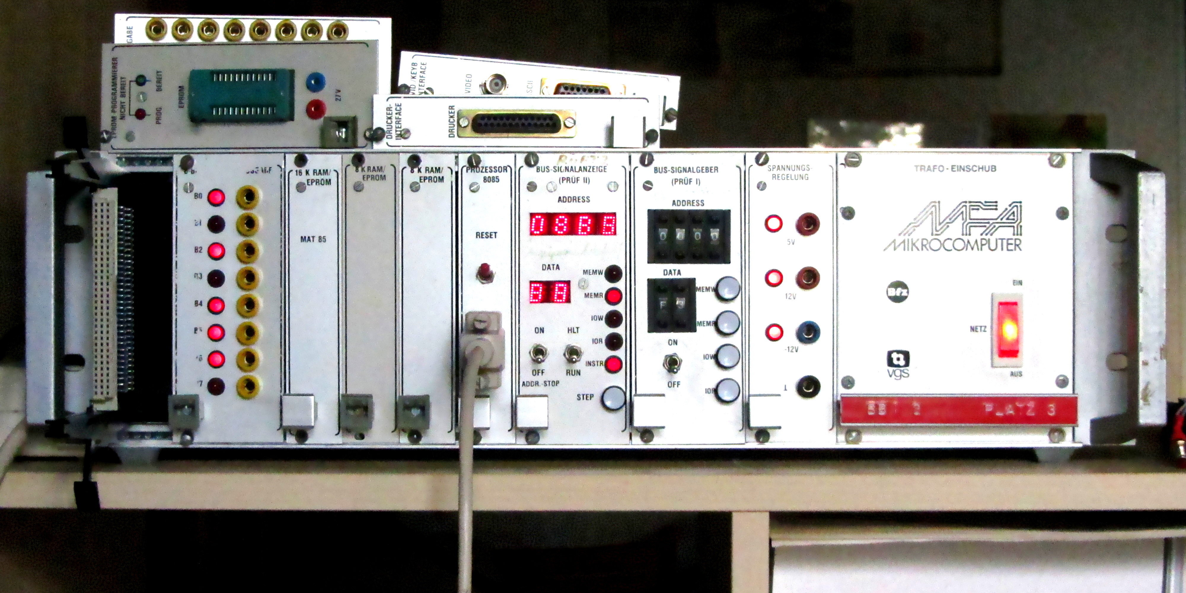
This table shows all the modules I own, but there are many more available than theese:
| Name | Number | Description | Specs | Picture | Frontpanel | Manual |
|---|---|---|---|---|---|---|
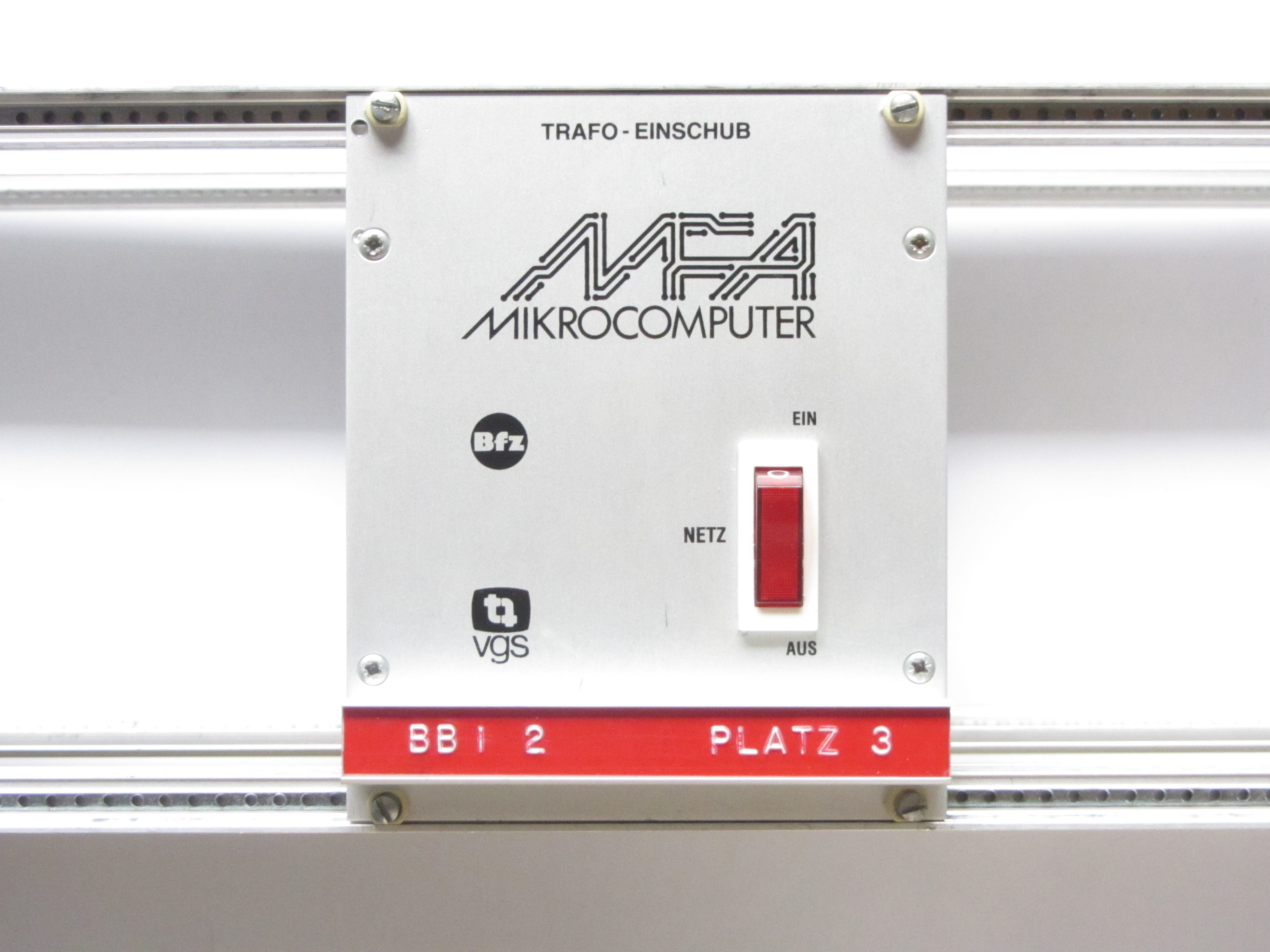
| TRAFO-EINSCHUB | 1.1. | This module is responsible for reducing and rectifying mains voltage for the "SPANNUNGS-REGELUNG"-module. | -Output voltages: +9V at 4A +15V at 0,5A -15V at 0,5A -Power switch -Fuse |
 |
 |
|
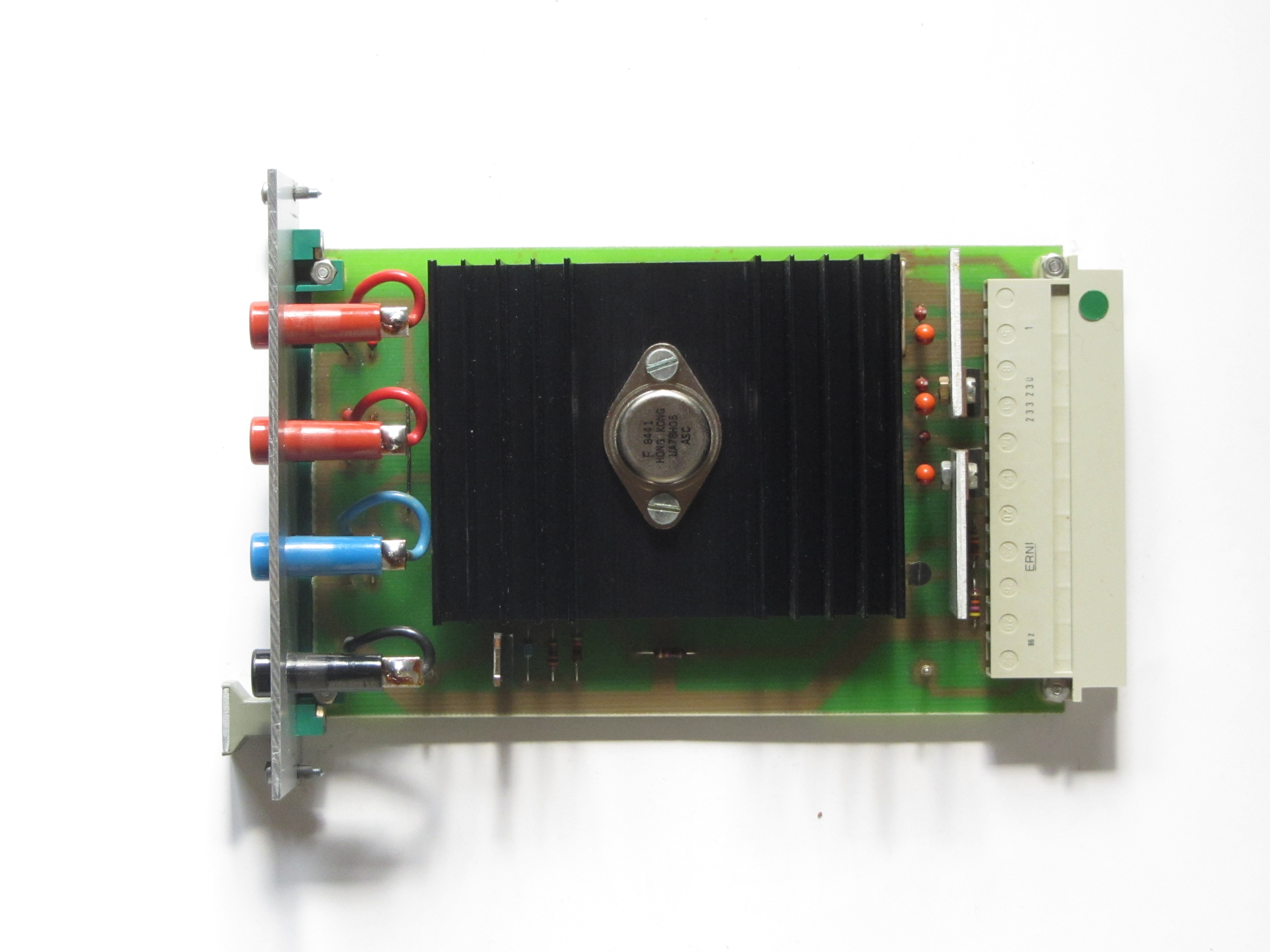
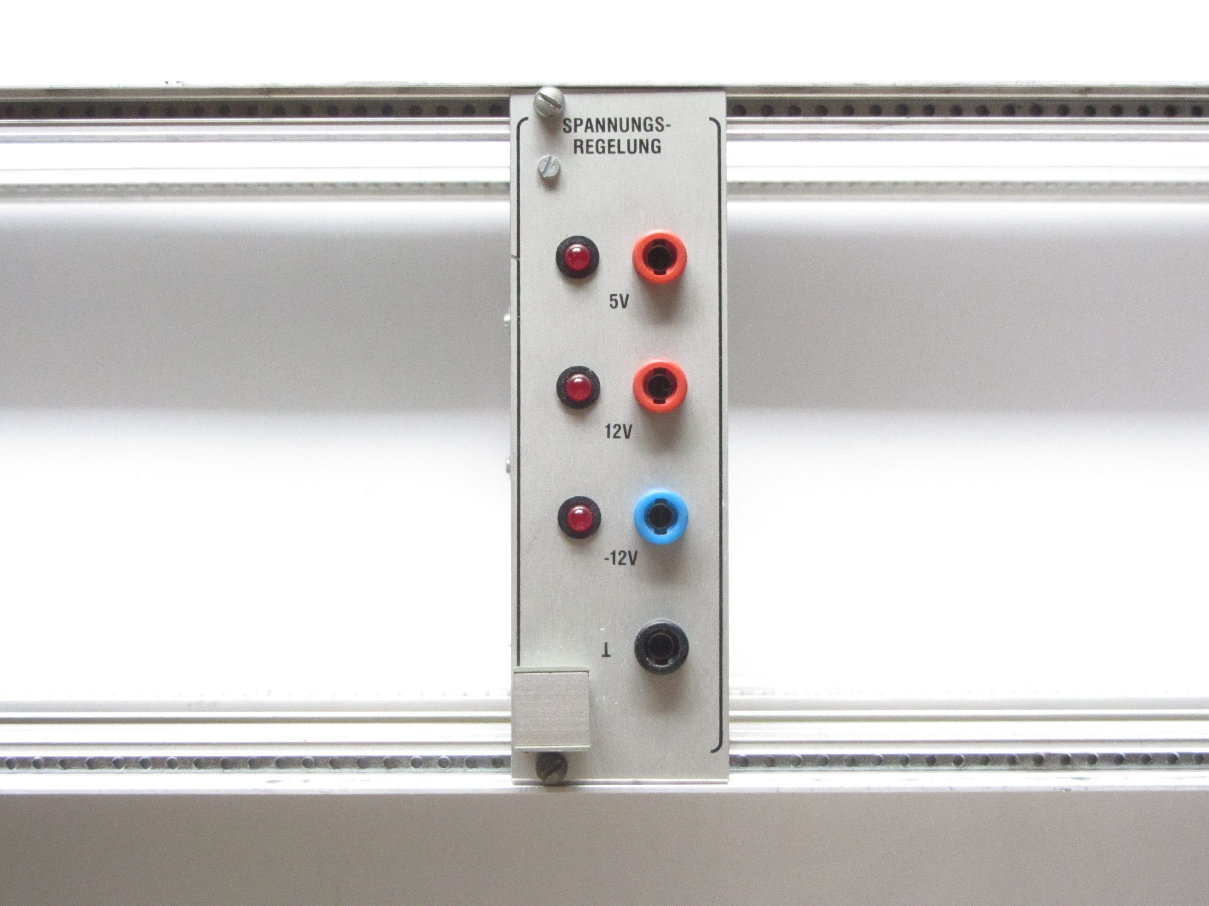
| SPANNUNGS-REGELUNG | 1.2. | This module takes the voltages recieved from the "TRAFO-EINSCHUB" and regulate them in a more precise way. | Output voltages: +5V at 4A +12V at 0,5A -12V at 0,5A -Overvoltage protection for +5V -100Hz TTL signal |
 |
 |
|
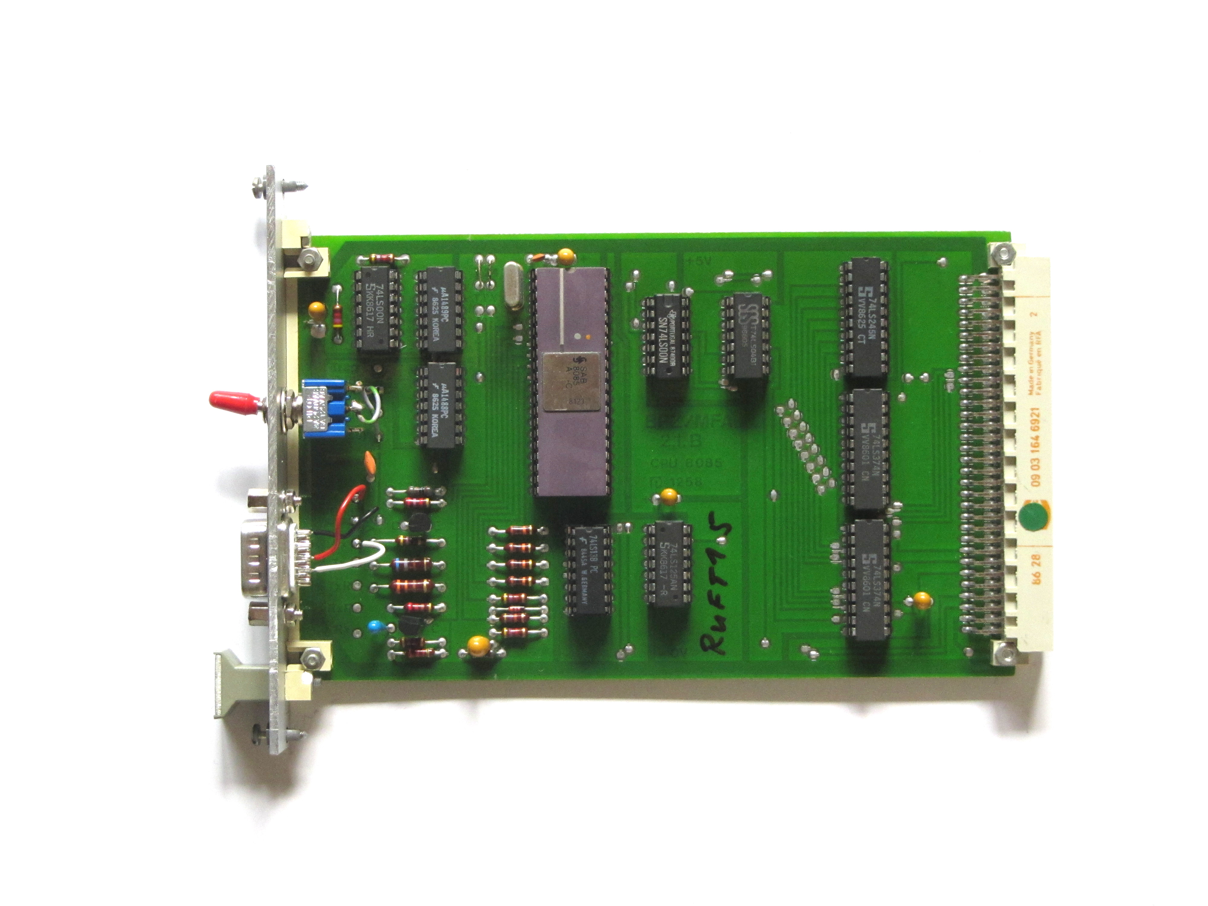
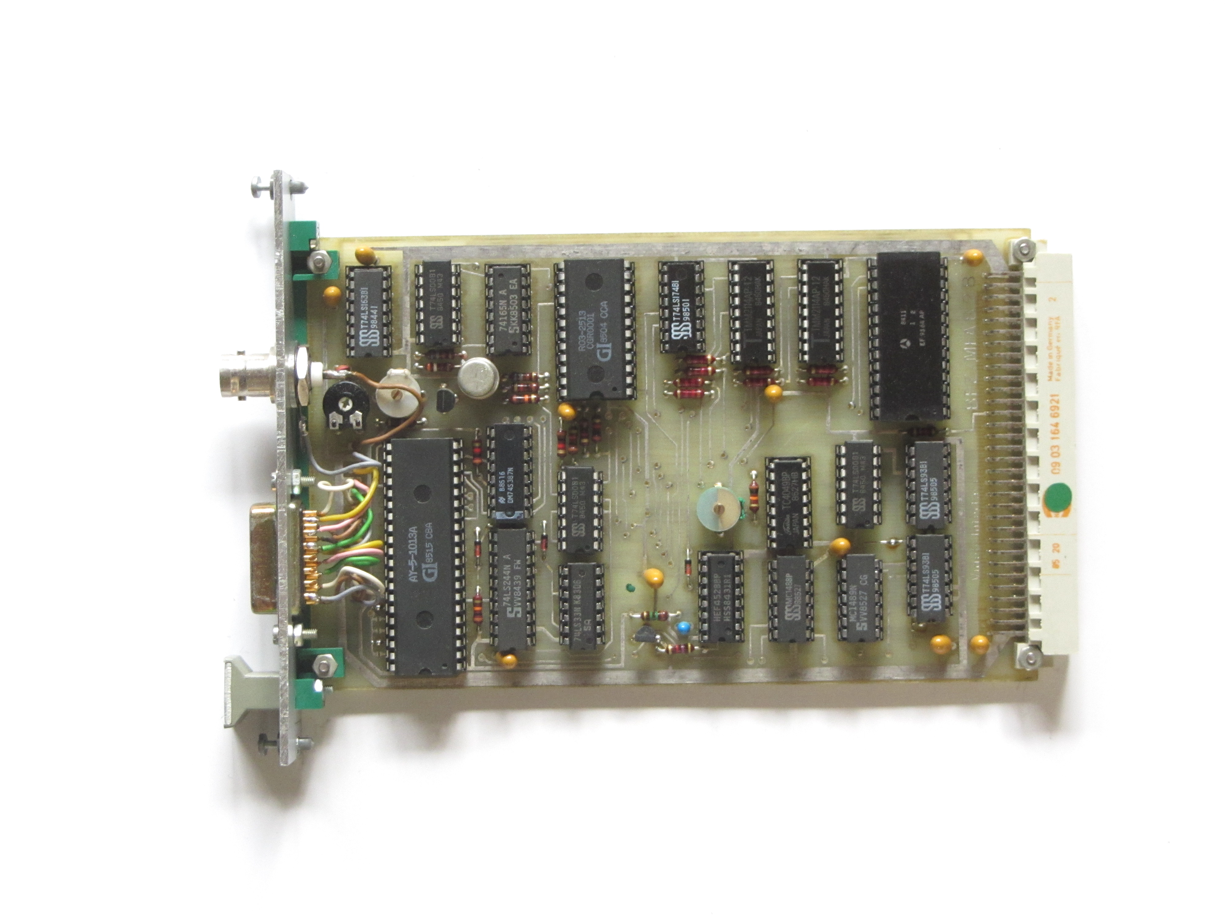
| PROZESSOR 8085 | 2.1. | This module is home to the CPU which does all the processing. The serial interface is connnected to the bus but I've also added a DE-9 Connector to the front for use with a terminal. | -Intel 8085 CPU -V24/RS232 interface -TTY interface -2MHz clock speed -Fully buffered bus |
 |
 |
|
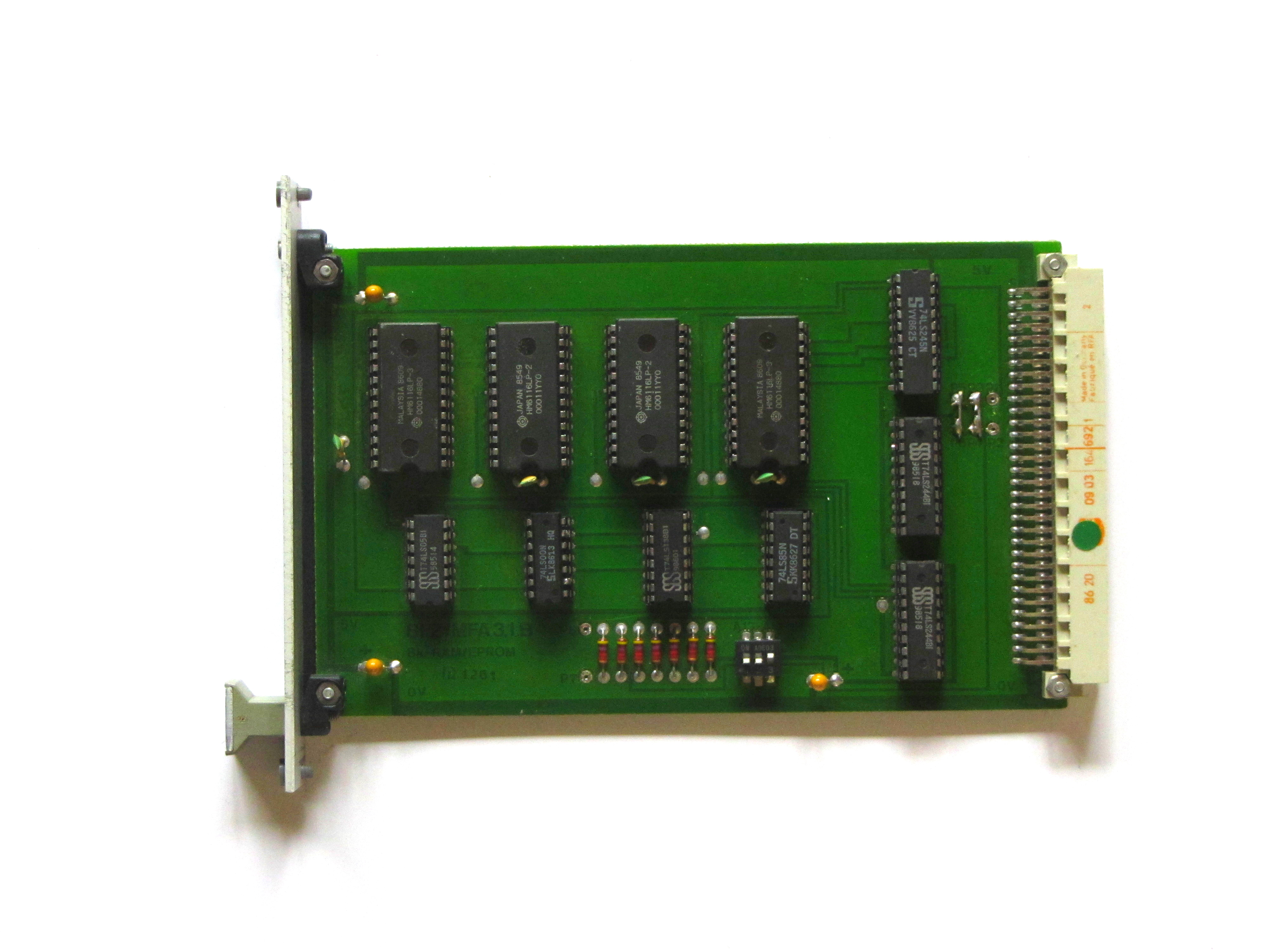
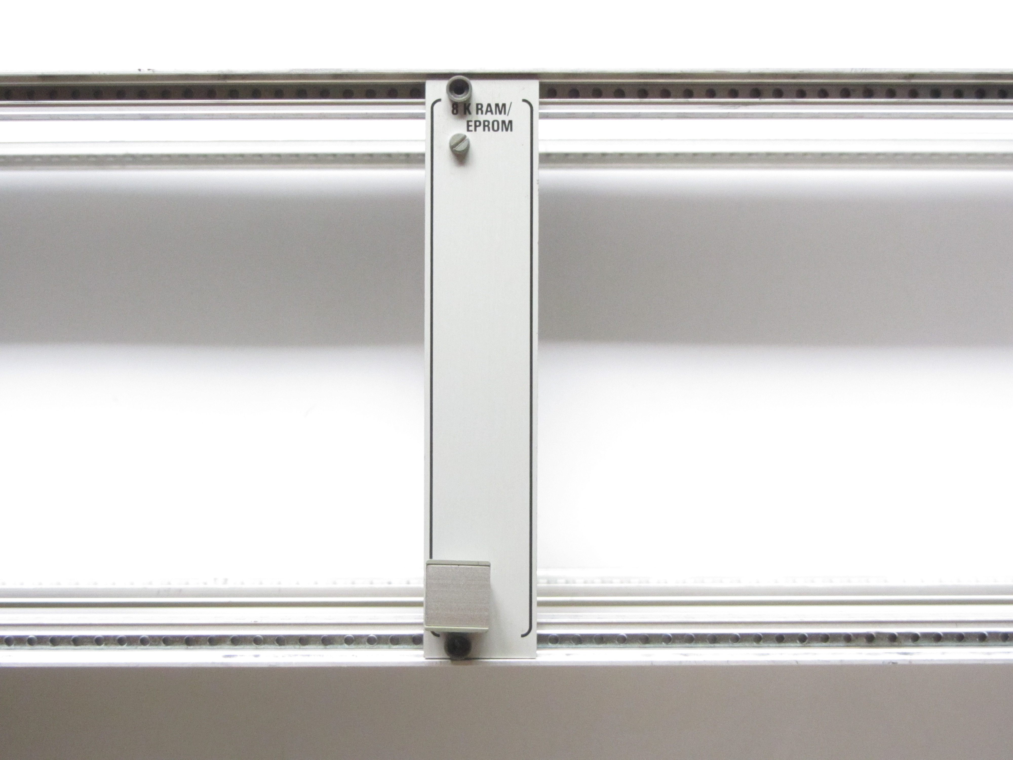
| 8 K RAM/EPROM | 3.1. | This is a rather simple module, it features 4x 2K memory chips, either 6116 RAM or 2716 EPROM. It can be placed every 8K steps in memory. | -4x 2K memory chips -DIP-switch for base adress -Buffered adress and data bus |
 |
 |
|
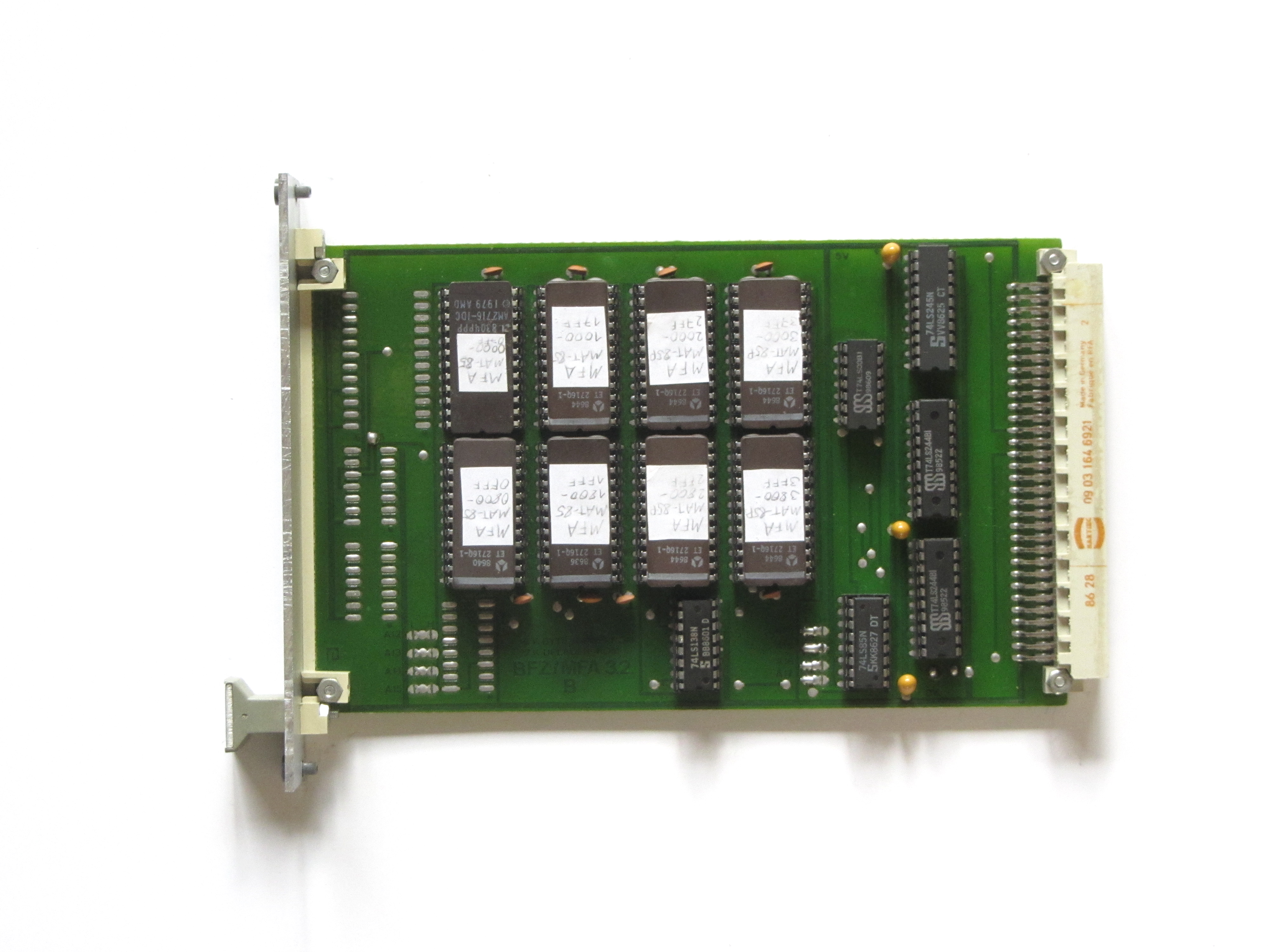
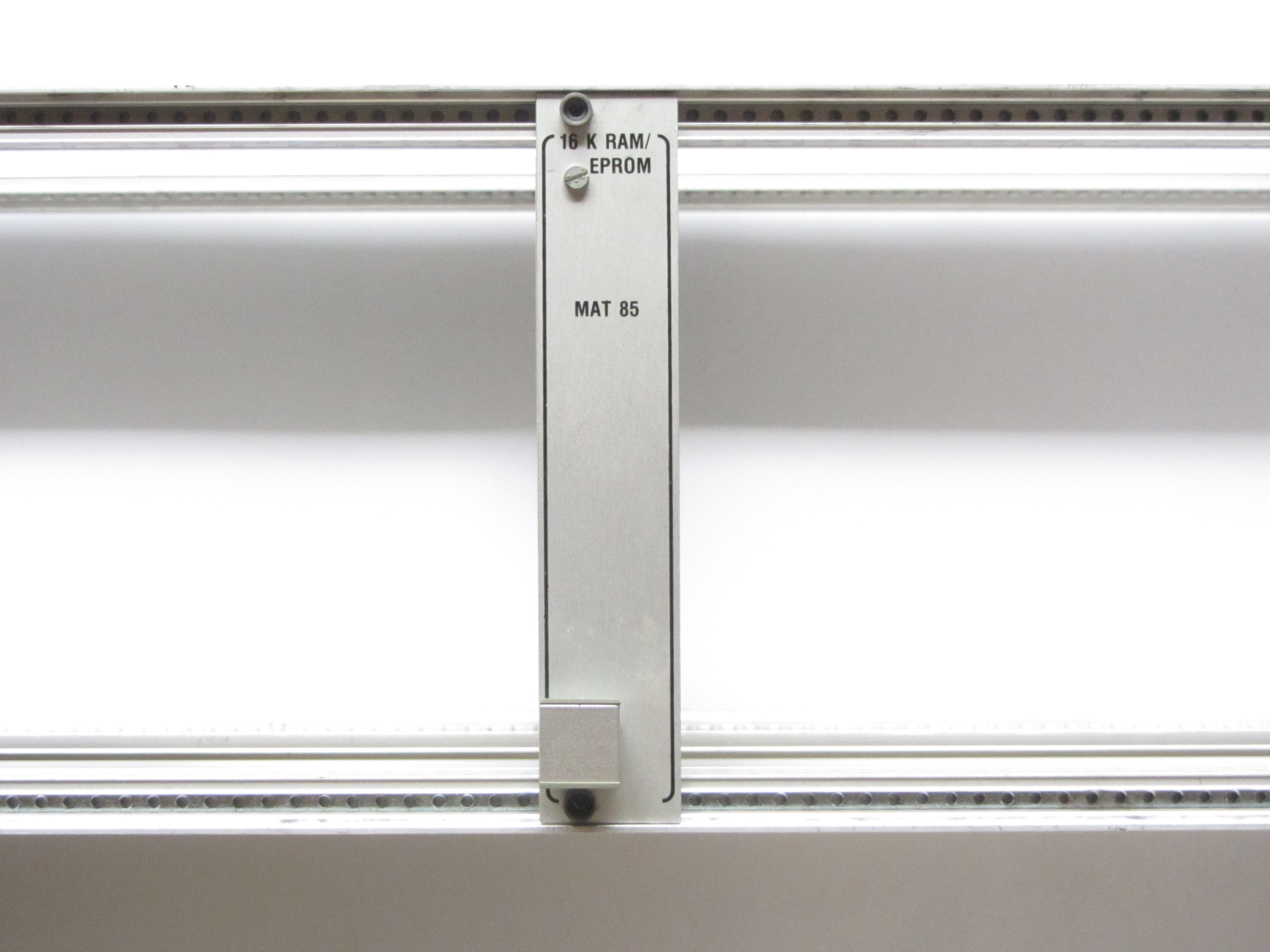
| 16 K RAM/EPROM | 3.2. | This module is similair to the "8 K RAM/EPROM" module, but with additional 4x 2K memory chips. It also features a otion for a bootloader EPROM wich can be used with DOSs. | -8x 2K memory chips -Jumpers for base adress -Buffered adress and data bus -Option for bootloader EPROM |
 |
 |
|
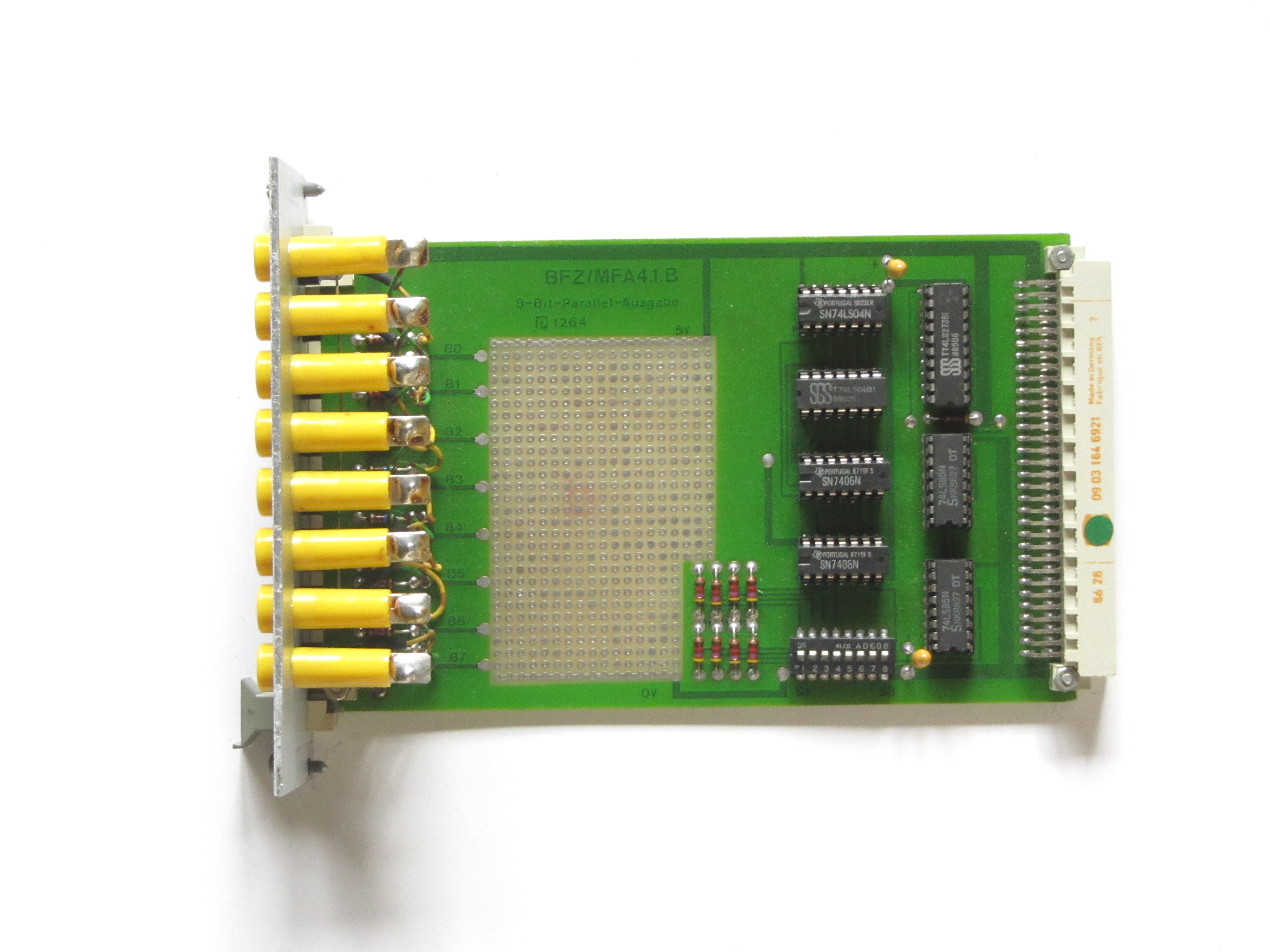
| 8-BIT-PARALLEL-AUSGABE | 4.1. | This module simply adds a 8-bit output port, displaying its status with LEDs and offering 8 output ports. | -8 output ports -DIP switch for I/O-adress |
 |
 |
|
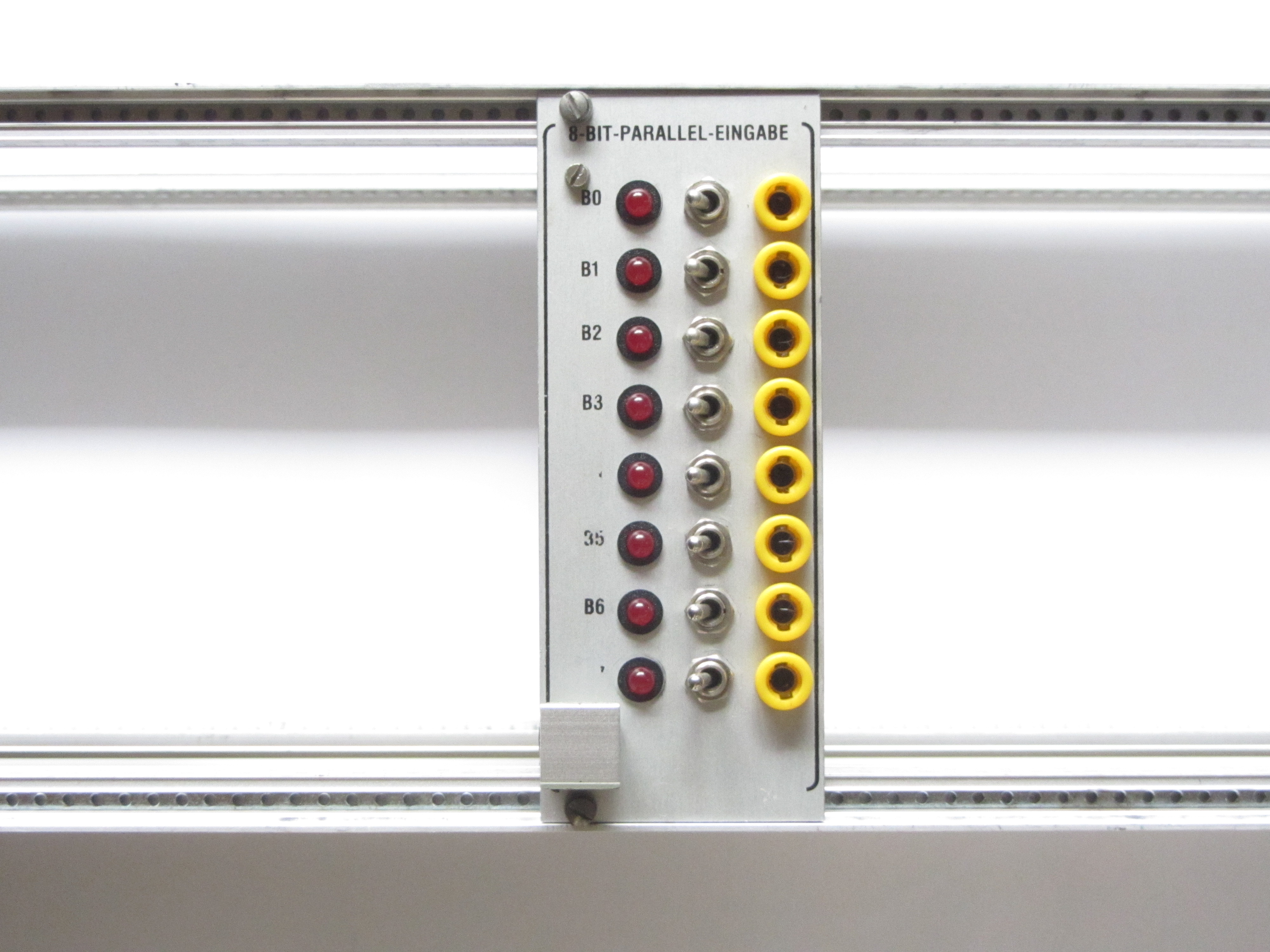
| 8-BIT-PARALLEL-EINGABE | 4.2. | This module is similair to the one above, but with inputs instead of outputs. An input is given by 8 toggle switches. | -8 input ports -DIP switch for I/O-adress -8 toggle switches as input |
 |
 |
|
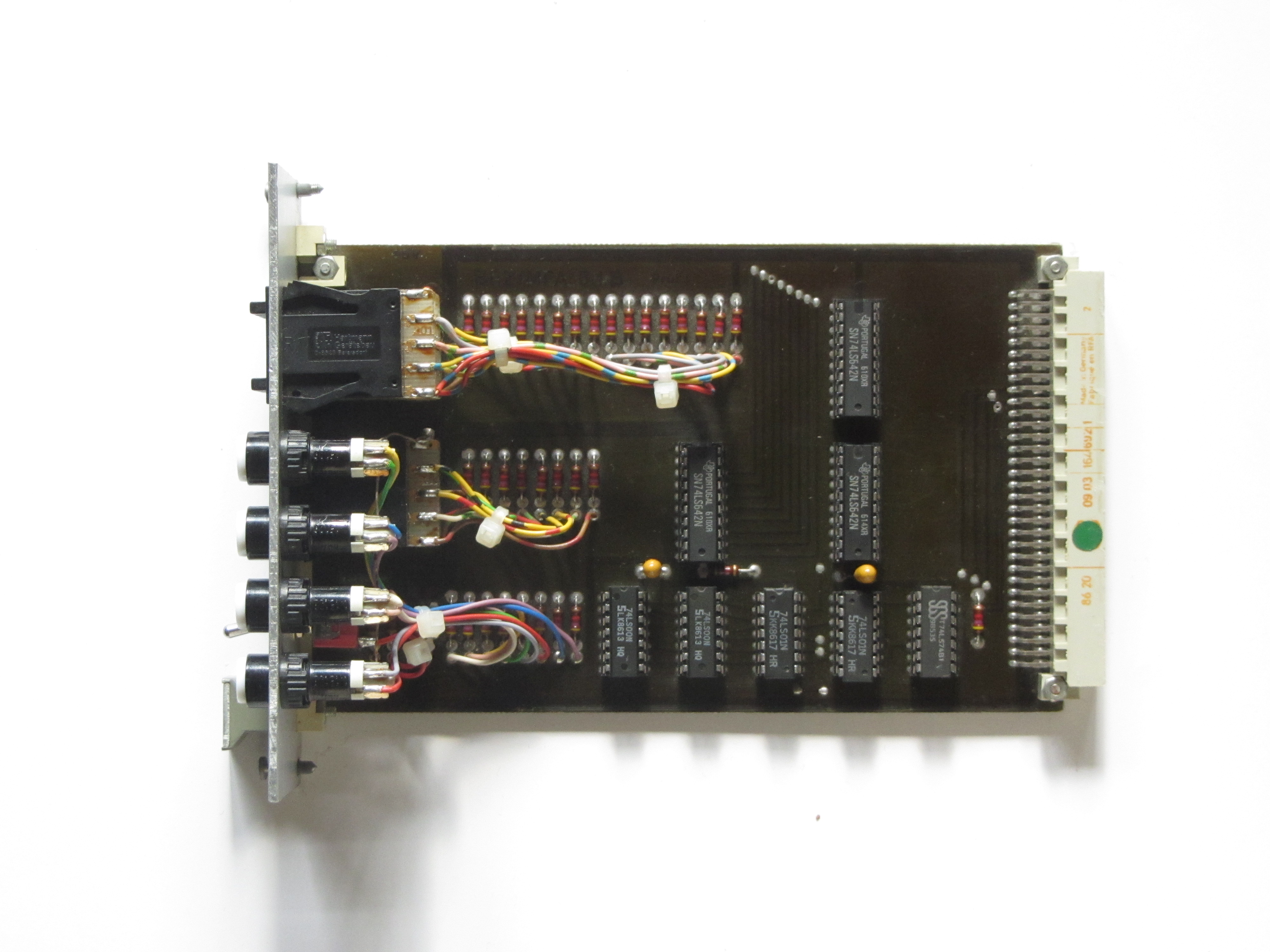
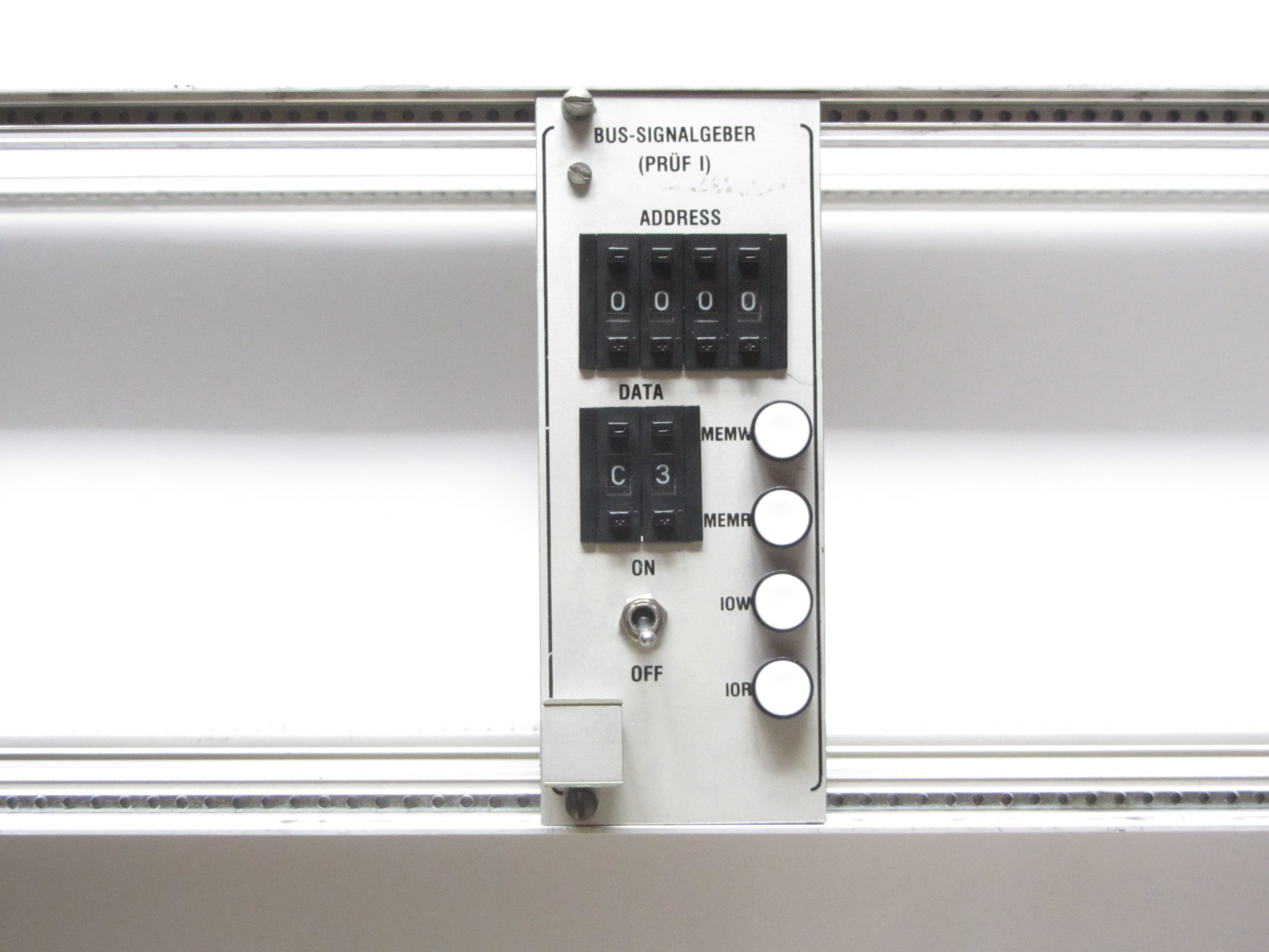
| BUS-SIGNALGEBER (PRÜF I) |
5.1. | This is a very neat module, with it you can access memory and I/O ports and write data. | -4 hex. adress switches -2 hex. data switches -IO/MEM read/write buttons |
 |
 |
|
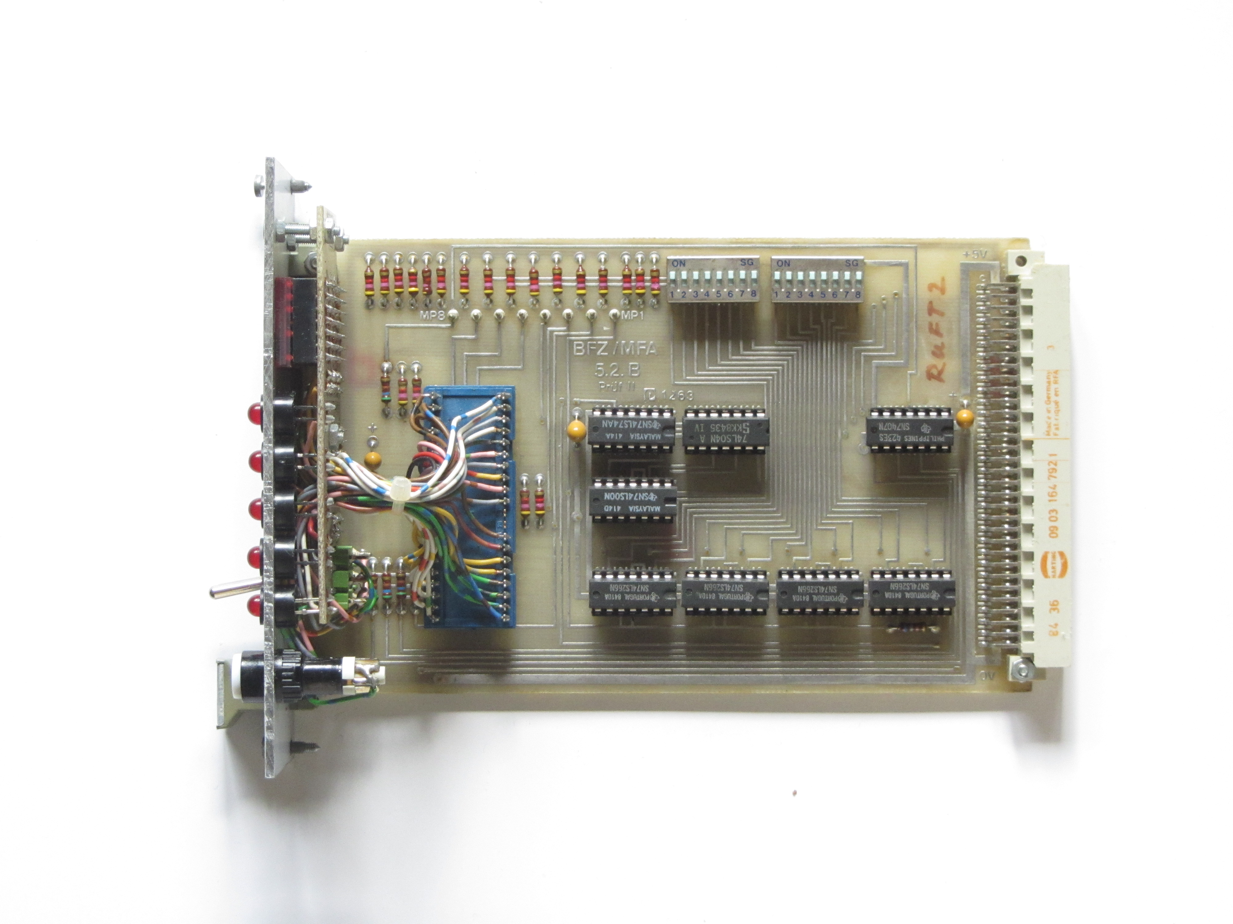
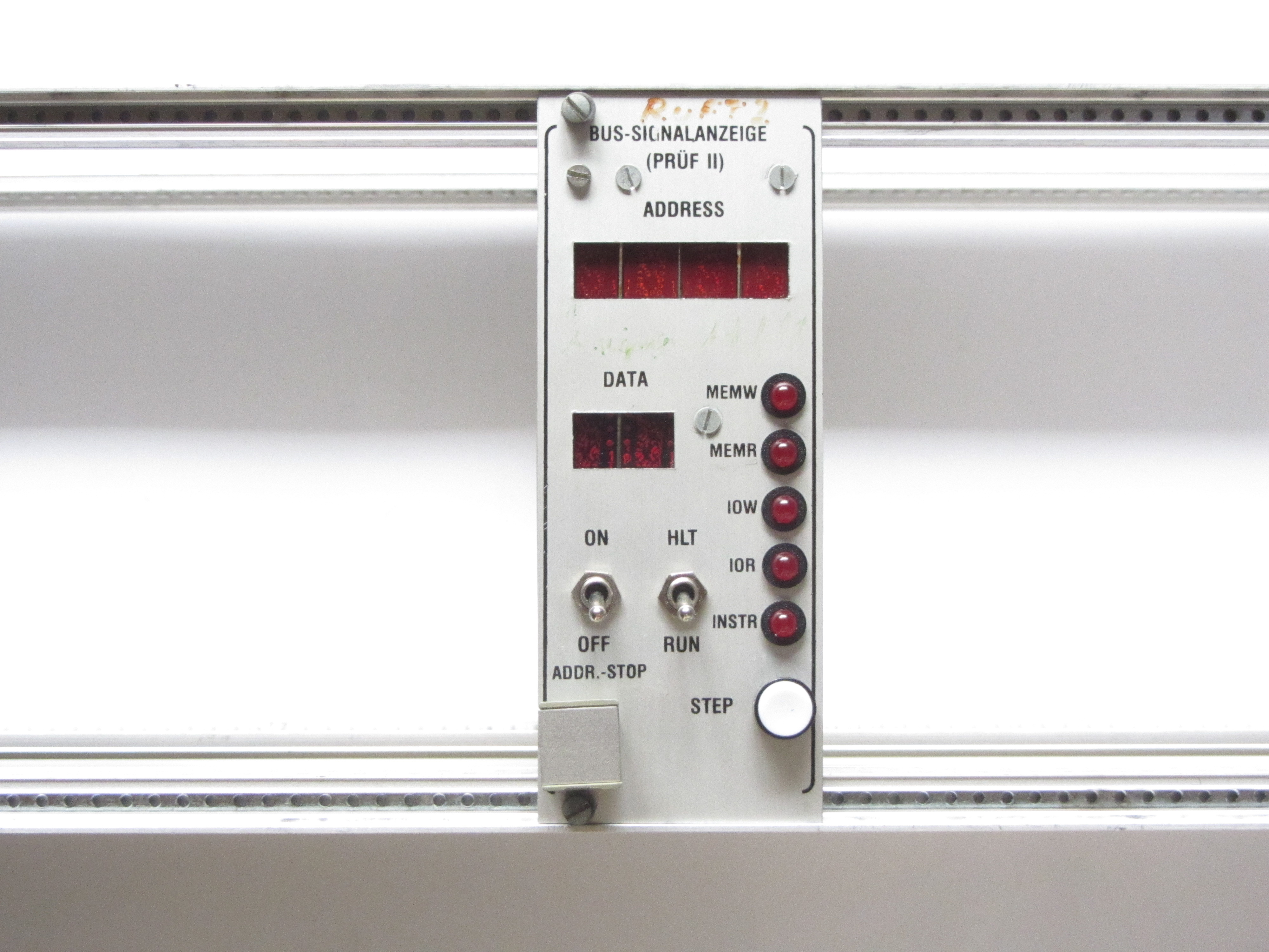
| BUS-SIGNALANZEIGE (PRÜF II) |
5.2. | With this module you are able to view the bus status and debug the computer/programs. You can single-step the CPU and make it stop at a specified adress. | -4 hex. adress display -2 hex. data display -IO/MEM read/write & Instr. LEDs -Single-step button -Addr.-stop |
 |
 |
|
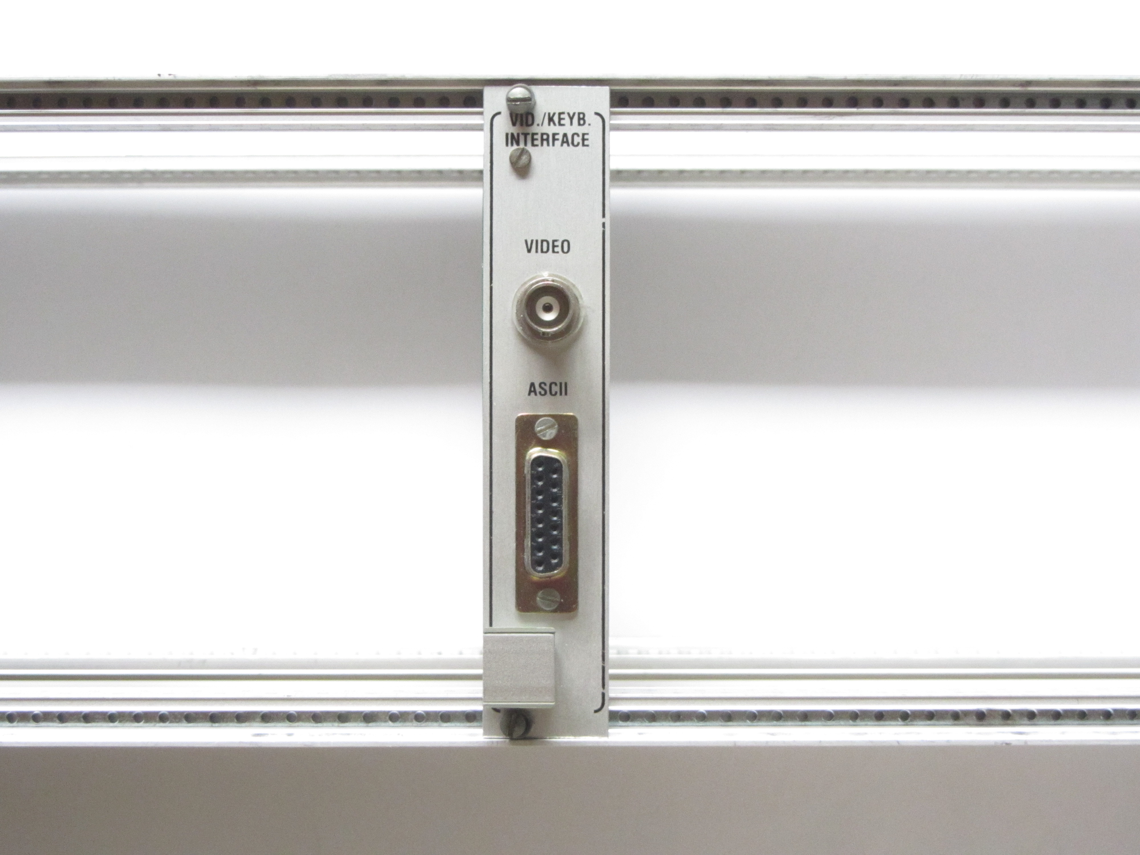
| VID./KEYB. INTERFACE | 8.2. | This module essentially is a very basic terminal, with a V24/RS232 interface, an ASCII-keyboard input, and a BAS video output(monochrome composite). | -V24/RS232 interface -ASCII-keyboard port -BAS video output -16x64 character display -5x8 pixel per character |
 |
 |
|
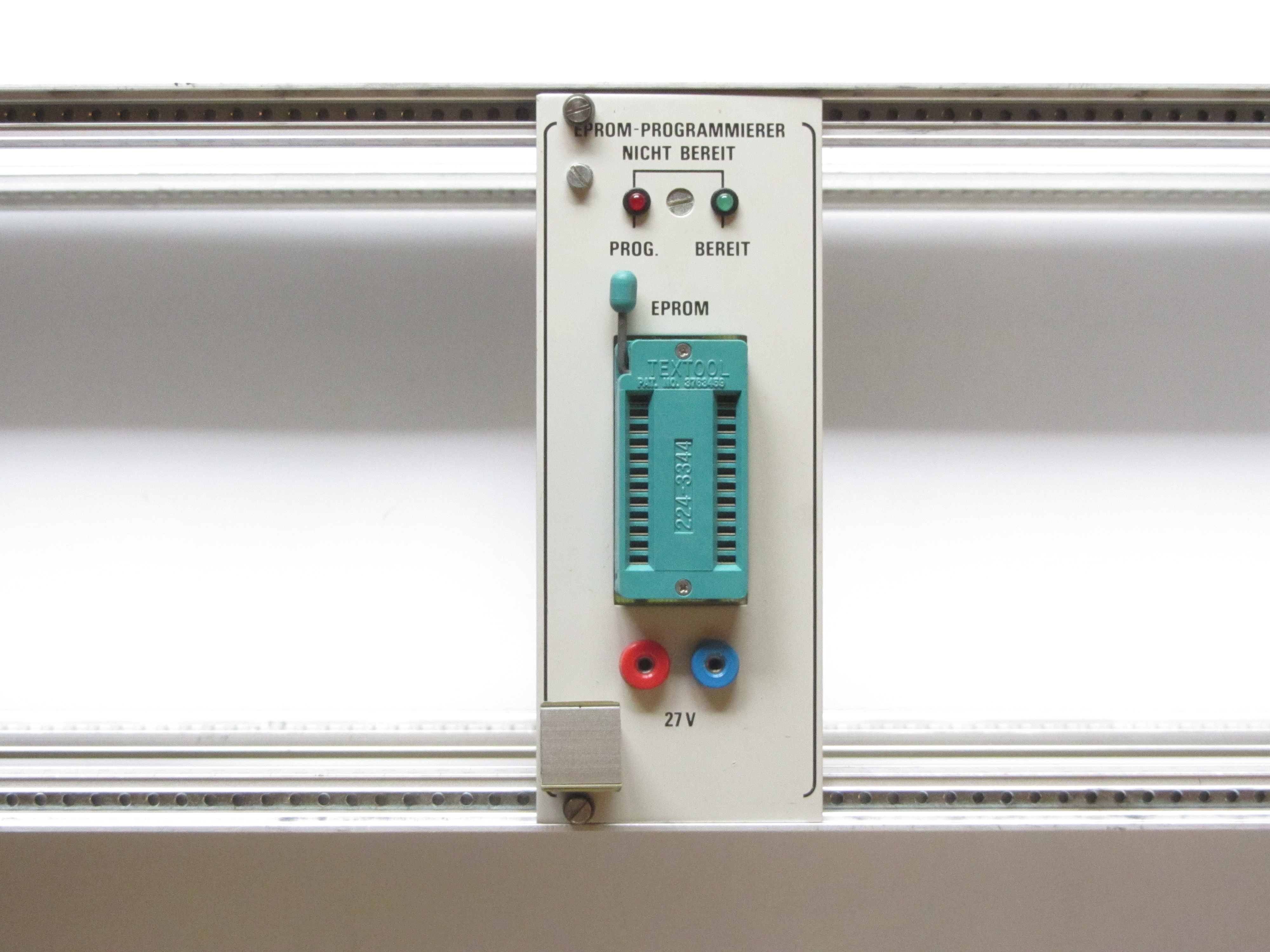
| EPROM-PROGRAMMIERER | 4.3.a | With the help of this module you are able to read and write 2716 EPROMs. The programming voltage however has to be supplied by an external source. | -Reads/writes 2716 EPROMs -Requires external 27V for programming -Status LEDs |
 |
 |
|
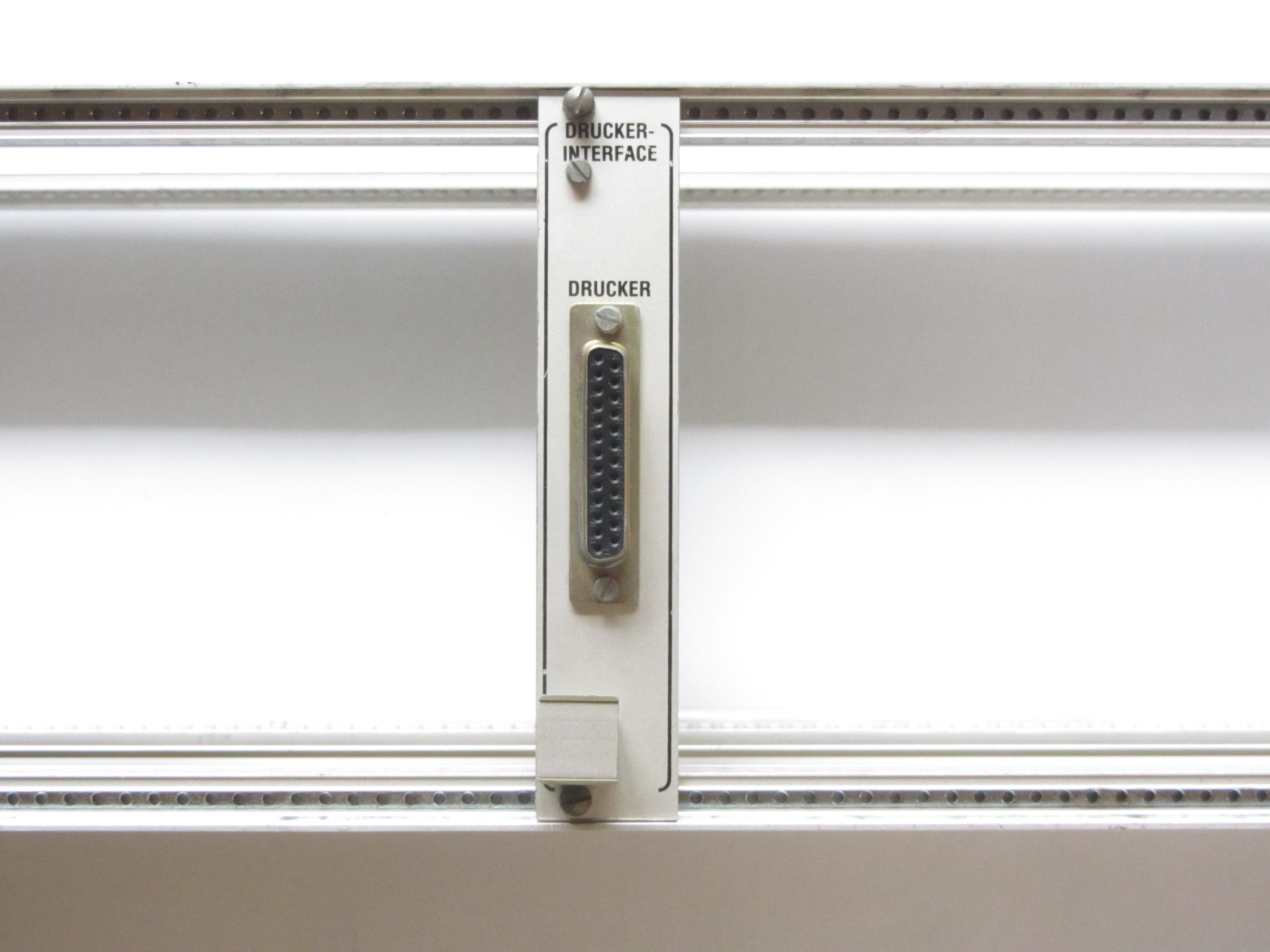
| DRUCKER-INTERFACE | 4.3.b | This module is very straightforward and just adds a printer interface to the computer. | -DB-25 printer port |  |
 |
|
| Adapterkarte 64polig | 5.3. | This is an extension card used to make testing or debugging any modules easier by mounting them outside of the case. | -64 pins -every pin can be interrupted |
 |
 |
Many more manuals can be found on oldcomputers-ddns.org, many thanks to fritzeflink who put all the effort in scanning and editing the documents and files.
This 8085 computer uses 64-Pin DIN 41612 connectors which have the following pin assignment:
The memory map is rather simple, the "MAT85" monitor program is placed at 0000H-1FFFH and only needs RAM at F800H-FFFFH. If the service pack "SP1" is also installed, you have to install additional RAM after 6000H to use BASIC, and RAM after E000H to use the SPS program.

On startup the system boots into MAT85 and lists all available commands. You can either hit the first letter to run that command or hit "Space" and enter the SP1. By hitting "H", the computer will list all commands available in the SP1. For example, by hitting "B" you enter the BASIC interpreter. If a program is beeing executed, you can hit the reset switch on the "PROZESSOR 8085"-module to get back to the command-line. No data will be lost if you reset the CPU.

This page was last modified .